spring calculation Q&A
Wire spring
– Common
How do I select materials?
-
Three types of materials can be selected by WEB Spring Calculation Programme: Stainless Steel, Steel and Copper.
The material characteristics of each are as follows.- Stainless steel material: Resists to rust (harder to rust) and is the most suitable material for first selection.
- Steel: Better durability and stronger load than stainless steel materials. However, since rust is likely to occur, plating treatment is required depending on the environmental conditions.
(high temperature and humidity, environmental etc without lubricating oils or grease) - Copper material: Excellent conductive material. It is mainly used for contact parts and products which dislike magnetism.
When used as a “spring” because of its soft material, its durability performance is low and its load is also low.
Further, since the rust and discoloration is likely to occur, plating treatment is required.
Classification Material Spring property Corrosion resistance Continuity Remarks Stainless steel SUS304WPB recommended ○ ○ × Because SUS304WPB is highly marketable and corrosion-resistant,Commonly used stainless materials.
Decrease in toughness is extremely small even in a low-temperature environment.SUS631J1-WPC Material with enhanced heat resistance by precipitation hardening treatment.
Procurement takes time due to low marketability.Iron materials SWB(60C) ○ × △ Compared to piano wire, it is less expensive.
Tensile strength, when 100% of SWP-B, becomes about SWB:76%・SWC:86%.SWC(80C) SWP-A SWP-B is a commonly used ferrous material because it is highly marketable and durable.
Tensile strength, when 100% of SWP-B, becomes about SWP-A:90%.
(SWP-A takes longer to obtain)SWP-B recommended Copper materials C5191W-H × × ○ Phosphor bronze for general springs.
Used for terminal springs, etc. that emphasize continuity.
It takes time to obtain materials. Please contact us separately.C1720W-3/4H Beryllium copper is used in products that place a high priority on continuity.
By the age hardening treatment, load and durability are higher than phosphor bronze.
It takes time to obtain materials. Please contact us separately.*Design using materials other than the above is also possible. Contact us for more information.
Depending on the material and marketability, the minimum ordering quantity and remaining materials may be purchased.
In such a case, we will contact us separately when making design consultations and making estimates. - Basic knowledge required for the calculations you want to know first
There are four main points.
Point 1 Load increase/decrease
- Wire diameter (d): The thicker the wire, the greater the load.
- The larger the mean diameter (D), the smaller the load.
- Effective number of turns (Na): The more the number of turns, the smaller the load.
[For compression springs]
- Free length (Hf): Longer the load becomes larger. (only when the load height does not change)
Point 2 for fracture
Relates to the allowable stress of the material.
If the allowable stress of the material is exceeded at the specified load, the material may be sagged or broken.Point 3 How to eliminate sag breakage
(1)You can change the material or (2) increase the wire diameter.
(1)When changing the wire, the “SWP-B” may be more durable than the “SUS304WPB” and may be able to solve the problem with the same wire diameter.
However, care must be taken because the load also increases.
(2)Increasing the wire diameter increases the allowable stress, which helps to eliminate the problem.
However, the mean diameter must also be increased.Point 4 How far can the diameter be reduced (increased)?
The maximum and minimum diameters vary depending on the spring index.
The spring index can be calculated by the mean diameter (D)/wire diameter (d).
The calculation formula for the mean diameter is shown below.
Mean diameter (D) = Inside diameter (ID) + Wire diameter (d) = Outer diameter (OD)-Wire diameter (d)The values of spring indices that can be processed are as follows.
5 ≦ Spring index (D/d) ≦ 24If the value falls below (exceed) this value, contact your nearest service center.
- Please tell me the drawing symbol.
Drawing symbols are as follows.
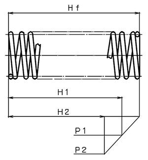
[Compression spring/conical coil spring]
Symbol Meaning ID Inside diameter D Mean diameter OD Outside diameter d Wire diameter Nt Total number of turns Na Effective number of turns Hf Free length Hs Solid length H Load height P Load D/d Spring index 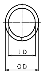
[Extension spring]
Symbol Meaning ID Inside diameter D Mean diameter OD Outside diameter d Wire diameter Na Effective number of turns Lf Free length L Load height P Load D/d Spring index 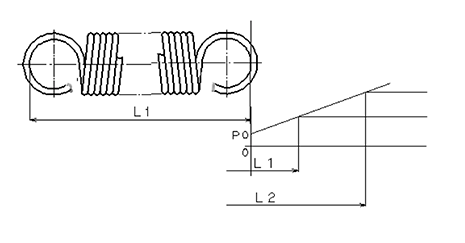
[Torsion coil spring]
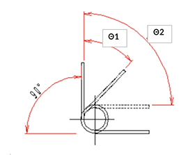
Symbol Meaning ID Inside diameter D Mean diameter OD Outside diameter d Wire diameter P Load N Number of turns Θ0 Winding angle Θ1・Θ2 Specified angle D/d Spring index 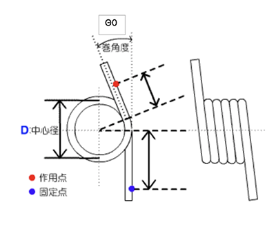
This is the number of life cycles during durability performance. Under what conditions will this be judged?
We are concerned about whether or not the answer has been made, but we do not consider various factors of severe environment (high temperature, low temperature, corrosion, vibration, impact, surging) as we design our products under extremely general use environment.
The test speed may also contain many factors.
In fact, even with 20000 calculations, there are actually 0.2 million cases, or in fact 20000 breaks.
This is a life test within extreme general factors, but even so much of the difference does not deny the factor part of the material, which is also an error from a multilateral point of view.
Therefore, our calculations are based on JIS B 2704 JIS B 2709, so we would like you to consider these calculations.In general, in spring manufacturing, the variation with respect to the design value is thought to be 10%. How much variation is assumed when this variation is taken into account in your spring calculation form?
We do not take the dispersion into account in our calculation formula at all.
However, when the spring is machined as shown in the drawing, the straight correction value, etc. is replaced and the calculated value is correlated with the actual spring.
In addition, although the amount of dispersion is assumed, it is quite different depending on the spring. If you inform us of the specific drawing, dimensions, and specifications of the spring, we will give you a reply. Please let us know how to do it.When we calculated the springs we are considering, we found that the allowable static load “no sag problem” and the estimated number of times of life “can be expected up to 50000 times.” In this case, do you think that the load change from the initial load does not occur even if you pile up the durability? Also, what percentage of change is expected when the load increases or decreases?
There are basic concepts regarding allowable static load and number of estimated life cycles.
Static load for cycles of 2000 cycles or less. In the above cases, emphasis should be given to the dynamic load (life cycle).
In general, the static load is used to check the deflection of the spring and the dynamic load is used to check the breakage of the spring.
In this inquiry, does the load change occur even if the durability is repeated? However, in the calculation (theoretical), it is considered that there is no change.
In particular, torsion springs have an advantage in that deflection in the direction of entrainment does not require stress correction. It is only a definition in the calculation, and conditions often deteriorate due to the material of the spring, processing method, low-temperature annealing treatment, etc. It is recommended to ask the “Spring Manufacturer” for production.
We are confident that we have acquired ISO9001 and are fully committed to providing high-quality products.
Please feel free to use it.
– Compression spring
What is the definition of buckling hazard? What is the % for?
-
Very complex formulas have been published in “Standards for JIS Springs” published by the Japanese Standards Association.
Of course, the section in which we asked us to examine the drawings has a variety of diagnoses using the calculation formula, but on our website, we simply call for the danger of buckling when the danger of buckling is “free height ÷ mean coil diameter” and “4” or more.
Conversely, when the value is less than “0.8”, it may be very difficult to process, so we judge it to be “under”.
In addition, all the values above are based on JIS, so please contact us for information on how to actually process them.
Then, the relationship between the aspect ratio and buckling is quite different even when the compression spring is supported.
If you contact us, we will diagnose how far can the height not buckle with the complicated calculation mentioned above? Please feel free to contact us. How much is the accuracy of the first load and the second load of the compression spring?
In addition, what is the relationship between this and the setting method?In the case of a compression spring, it is said that the upper and lower 30% of the total deflection from the free length to the crimp height does not stabilize the constant. In other words, if the first and second loads are set between 30% of each, the accuracy becomes unstable.
In addition, the actual diameter of the material will also change from the calculated diameter to the micron range. Therefore, the deflection of the constant will affect the accuracy of the first and second loads.
The instability of the mean diameter and the number of turns also affects the process. However, we are pleased to have some tolerances on the number of turns and the mean diameter in the process, since we will process according to the load in reverse.
Setting refers to an operation that applies a load to the spring to cause a certain degree of permanent deformation, thus increasing the elastic limit of the spring. This will have the effect of stabilizing the load.
We have made the general answer mentioned above, but please understand beforehand that the values of the coefficient (mean diameter ÷ wire diameter) of the spring and the value of the aspect ratio (free length ÷ mean diameter) are all changed.
– Extension spring
How do I need to specify the load when I want to calculate the tension by the external dimensions in the tension spring calculation?
As you know, extension springs have tension. (The force to keep the wires in close contact with each other even under no load) Even if the tension spring is of the same shape, the load strength can be changed by changing the initial tension within a certain range.
Therefore, what level of initial tension should be used to produce the required load for the size of the product being designed by the customer?
As mentioned above, since the initial tension is adjusted within a certain range, it is impossible to increase or decrease the tension infinitely. Therefore, in actual production of springs, it is necessary to specify the load in order to verify whether machining is possible or not.What is the reference load value and the actual load value shown in the calculation result of tension spring?
In the calculation result of the load of the extension spring, the result that proper evaluation of the initial tension is difficult to process is displayed. Is this a spring that cannot be made even when the actual load is displayed?When machining tension springs, the calculated initial tension and the actual machinable initial tension range are usually different.
The ideal value is calculated (100%), but it is said to be 20% to 200% after adjustment.
However, if the tensile strength is as high as 300%, processing is also possible depending on the product. In such a case, please contact us. We will verify it.
It is calculated in the range of general initial tension ratio, and the result is clearly shown in COOL.
We will be able to help you with the design if you consult with us.In the load calculation results for the extension spring, the initial tension suitability evaluation displayed a result of “difficult to manufacture.”Does this mean that even though the actual load is displayed, it is a spring that cannot be made?
When processing extension springs, the calculated initial tension and the range of initial tension that can actually be processed usually differ.
The ideal is to match the calculation exactly (100%), but it is said that adjustments can be made within a range of 20% to 200%.
However, if it is a high tension of around 300%, processing may be possible depending on the item, so please contact us in that case.
We will verify it on our end.
We calculate within the range of general initial tension ratios and clearly present the results objectively.
Please feel free to consult with us, and our company will be happy to assist with the design.
– Torsion spring
What is the height of the coil part of the torsion torque calculation result?
-
In our calculation formula, the height of this coil part represents the height at maximum entrainment, not the height in free state.
In other words, when the wire diameter is φ0.45 with a two-turn torsion spring, the helical section height is “1.35mm”. When the winding angle is 180 degrees, 0.45 x (2 + (180/360) + 1) = 1.575mm.
This is a case that is misunderstood when inputting for the reason of the shortage of our explanation. When inputting the number of turns, “2.4 turns” or “2.75 turns” are input, then “144 degrees” or “270 degrees” are input. In such a case, the number of turns in the natural state (when free) is added to “2.8 turns” or “3.5 turns”.
If such misunderstanding is found, enter a numerical value with no decimal point (natural number 1, 2, 3, etc.) and enter the part involved in the numerical value in the field of the winding angle.
In the case of the above example, please enter as the number of turns “2”, the winding angle “144” degree and “270” degree.
For φ1.0mm wire diameter, 10 turns, 90 degrees of winding angle, and 180 degrees of winding angle, the coil section height at the time of freedom (natural condition) is 11.25mm, and the coil section height at the time of max. winding is 11.75mm. Regarding the deflection angle of the torsion spring calculation (What refers to the first deflection angle and the second deflection angle?)
Regarding the first deflection and second deflection in your inquiry, please refer to the figure below.
In the case of the product shown in the figure, the figure shown with a solid line indicates that the product is free of any load. We think that the moment or load is important when you put it to the position A and B in your use condition. However, the movement angle to A and the movement angle to B are the “deflection amount”.
There are various methods for free time when the moment does not come out to the required value… One of them is to reduce the winding angle of free time (reduce 90 degrees) and increase the amount of deflection…
About calculation formula of tension spring
A. Which formula is used to determine the bending stress?
B. Where is the standard for allowable static load judged?
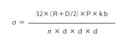
C. What is the criterion for evaluating the estimated number of life cycles?Equation for calculating stress
When used in the winding direction.
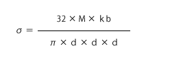
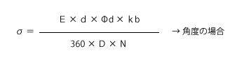
When using in rewinding direction.
B. Criteria for allowable static load
Multiply the smallest JIS tensile strength of each wire by each factor.
C. Criteria for estimated life load
The upper and lower stress coefficients (τmax or τmin /σB) are obtained and derived in the Guttman diagram.I think that there are two types of torsion springs: the winding type and the rewinding type. In the case of the rewinding type, leave a space in the column in the load direction and insert the deflection angle with respect to the winding angle in the minus angle? For example, when the winding angle (state without load) is 0 degrees and the deflection angle is the rewinding direction, etc.
In the calculation, the item “Load direction” is located below the second deflection angle.
Check this box to calculate the entrainment type. Uncheck this box to calculate the rewind type. In other words, you can leave it blank as you wish.
However, if this check is cleared, the numerical value for which deflection is entered will be calculated in the rewind direction, so no negative input is required.
Also, regarding the winding angle, consider it as the winding angle of the coil section.
Flat spring
Where do you know the availability of materials?
-
Refer to the “(Link) of Available Materials and Weight.”
In addition, the availability is displayed in the “Material availability” column for each material/thickness selected at the time of calculation. The desired material is not on the list.
If you consider using materials not listed, please contact us separately.
Please (Link) here for inquiriesHow do I calculate if there is only one level of opening width in use?
Enter the value of “Initial Opening Width” in “Opening Width (1)” in the calculation items, and enter the value of the specified opening width at the time of use in “Opening Width (2)” in the calculation items.
*In this case, the image is used between the initial opening width ⇔ working opening width (2).Cannot satisfy the desired load value.
When designing, consider the following as design tips.
– Relationship between load, stress and plate thickness, plate width and deflection
Thickness: Effective to load by the third power
Be effective in proportion to stress
(If the plate thickness is 0.5mm→0.8mm, 0.8^3/0.5^3 = 4.1 times the load is generated.)Width: Proportional effect on load
The stress does not change if the whole width is constant.
(If the plate width is 1.0mm→2.0mm, twice the load is generated.)Deflection: Effect proportional to load and stress
(If the deflection is 1.0mm→2.0mm, double the load is generated.)From the above, we recommend examining the following procedure.
(1)Increase the plate width within the allowable range in the specifications.
(2)Minimum required deflection is set while considering dimensional tolerances
(3)Increase the plate thickness to match the target load.
(If excessive stress occurs, it is highly likely that it will not hold in the current shape.)
(4)Make fine adjustments with the amount of deflection*Please note that this is not necessarily a shape that can be realized because it is necessary to design the product in consideration of its durability.
Design should be balanced against durability performance.How can I choose a material for tempering?
The properties such as the strength (tensile strength and hardness) of the material change depending on the tempering.
Refer to the following for the distribution of material tempering.Soft
Tempering symbol
Hard
1/2H
3/4H
H
EH
*The classification of tempering differs depending on the type of material.
Soft temper ⇒ Workability “○” Durability “△”
Hard temper ⇒ Durable “○” Workable “△”As mentioned above, the workability and durability may be affected by the tempering process.
Thank you for your reference and for your calculation. First, we recommend that you consider using the softest material (such as 1/2H).For free-access customers, a softer tempering is set in advance and calculated.
Upon receiving an inquiry, we are also able to propose specifications for other tempering methods in consideration of durability and other factors.