Environmental Risk Management
Creating environmentally friendly products
The company enforces strict management of its three-pronged rule of “not including, not using and not discarding” substances that are harmful to the environment, and is engaged in the promotion of environmental quality alongside product quality.
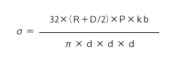
Changeover to washing liquid with less environmental impact
 Washing unit utilizing hydrocarbon-based product
Aimed at environmental risk management, our factories have been involved in preventing contamination from and reducing the use of trichloroethylene to wash products and die. Advanex is pleased to report that a switch from trichloroethylene to a hydrocarbon-based washing liquid has now been completed.
Green partners
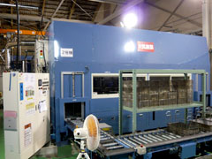
 Supplier briefings
Advanex holds various briefing sessions with its business partners as it is very important that we know how they also manage environmentally harmful substances to observe the regulation.
Supplier alliances
In order to prevent prohibited substances found in treatment surfaces being used, the company also focuses its attention on plated products. Advanex inspects the plants of surface treatment companies before listing them on our company register.
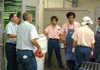
Emergency procedures
Emergency training
Corporate activities deployed by the Advanex Group are not oblivious to the risk of natural disasters such as floods and earthquakes.
 Emergency trainin
All employees participate in emergency training once a year so as to prevent and lessen the impact of a crisis situation. Training involves the prompt extinguishing of fires, evacuation, reporting to the local neighborhood and reporting to administrative authorities.
Entire Group engaged in the environment
The Advanex Group was quick to introduce ISO-14001 and continues to actively implement these standards.
ISO-14001 acquisition situation of ADVANEX Group
| Japan | Acquisition date | Certifying Institution |
| ADVANEX Niigata Factory | 2000年10月 | DNV |
| Overseas | Acquisition date | Certifying Institution |
| Advanex (Thailand) Ltd. | June, 2006 | SGS |
| Advanex (Dalian) Inc. | January, 2005 | TUV |
| Advanex (Dongguan) Inc. | February, 2005 | DNV |
| Advanex (Shanghai) Inc. | May, 2005 | SGS |
| Advanex (Singapore) Pte. Ltd. | July, 2005 | SGS |
| Advanex Europe Ltd. | March, 2008 | BSI |
| Advanex Americas, Inc. | July, 2006 | Interrek |
| Advanex (Vietnam) Ltd. | April, 2012 | SGS |
| Advanex (Changzhou) Inc. | May, 2014 | SGS |
| PT. Advanex Precision Indonesia | November, 2014 | JAS-ANS |